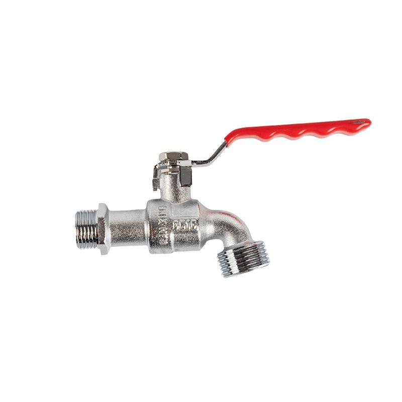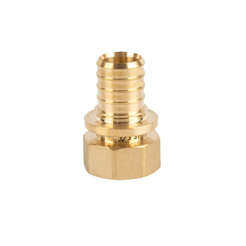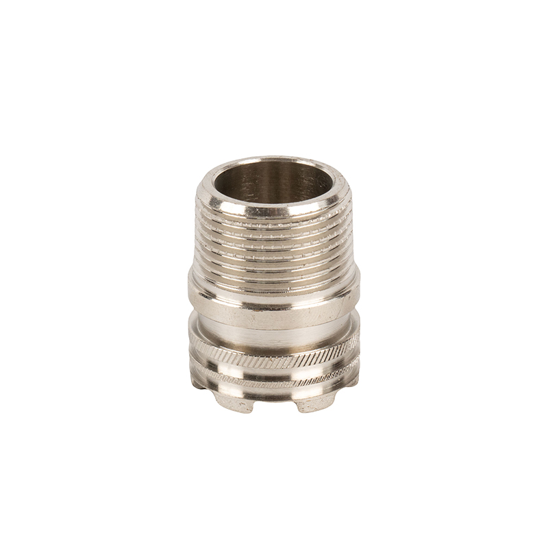

A brass insert fitting is one of the cheapest components in a plumbing system and one of the most expensive to get wrong. It is usually installed behind drywall, under a slab, or inside a cabinet, and its failure mode is rarely dramatic: a slow weep at a crimp ring, a hairline crack at the base of a barb, a pinhole that opens after two heating seasons. By the time anyone sees the problem, the fitting has been in service for years and the cost has moved from a few cents of brass to a remediation claim.
That asymmetry is why quality control on brass insert fittings cannot be a final visual check before the carton is sealed. It has to be a chain of gates: alloy verification at incoming, tool and process control in machining, dimensional inspection at the bench, destructive and pressure testing in the lab, and documentation that survives an audit. This guide walks through each gate and what to measure at it.
The article assumes fittings for potable-water PEX or PE-RT systems — barbed insert fittings, insert elbows and tees, and insert-to-thread transitions — but the same framework applies to brass fittings used in hydronic, irrigation, and compressed-air lines.
Most field failures blamed on "bad brass" are actually interface failures. An insert fitting is one half of a mechanical joint; the crimp ring or sleeve, the tube, and the tool are the other half. A fitting can be perfectly within its own drawing and still leak if the barb profile does not match the ring, if the tube is not pushed to the shoulder, or if the crimp tool is out of calibration.
For QC purposes, this means four failure families:
Joint integrity. Barb diameter, barb pitch, barb height, lead-in chamfer, and insertion depth determine whether the ring compresses the tube onto the barbs correctly. A barb that is 0.1 mm under size, or a lead-in that is too sharp, can produce a joint that passes a five-minute pressure test and fails after a hundred thermal cycles.
Wall integrity. Cast or forged bodies can carry porosity, cold shuts, or cracks at the hex corner. These are invisible on a plated part and only appear under pressure or in a cross-section.
Thread integrity. NPT and BSP threads are not interchangeable, and a worn die produces a thread that engages by hand but weeps under 60 psi. Thread form, crest condition, and thread length all matter.
Material integrity. The two failures with the longest tail are lead content above the potable-water limit and dezincification in aggressive water. Both are chemistry problems that no amount of dimensional inspection will catch.
Define the acceptance criteria before you inspect anything
Inspectors cannot reject a part against a feeling. Before the first lot ships, the buyer and supplier should agree on a document set that pins down four things:
1. A drawing that marks critical characteristics. Not every dimension deserves the same attention. Barb geometry, thread form, bore diameter, and material are critical; overall length and hex cosmetics usually are not.
2. A pinned standard edition. For PEX insert fittings, that typically means ASTM F1807 (metal insert fittings with a copper crimp ring) and the system-level tests in ASTM F877, with CSA B137.5 for the Canadian market. For expansion-style fittings, ASTM F1960. Threads are governed by ASME B1.20.1 (NPT) or ISO 228-1 and ISO 7-1 (BSP). Potable-water compliance runs through NSF/ANSI 61 and NSF/ANSI 372. Pin the edition and the year in the purchase order, because requirements move.
3. A defect classification. Critical, major, and minor defined in words the factory can apply on the floor.
4. A control plan. Which characteristic is checked at which gate, with which gauge, at what frequency, by whom.
A workable classification for this product family:

Everything downstream is built on the rod or the casting, so this is the gate with the highest leverage and the one most often reduced to "the supplier sent a certificate."
Chemistry and alloy identity. For machined fittings, brass rod is commonly specified to ASTM B16 (free-cutting brass) or a lead-free equivalent such as C27450, C28500, C69300, or C89833. Note the distinction that trips up a lot of buyers: "lead-free" under NSF/ANSI 372 means a weighted average lead content of no more than 0.25% across wetted surfaces, not zero lead. A C36000 free-machining brass — roughly 61.5% copper, 3% lead — machines beautifully and fails that requirement outright. If a quotation looks unusually cheap for a lead-free part, the first question is which alloy is actually being run.
How to verify it. Handheld XRF is a fast screening tool and belongs at goods-in, but it reads the surface and can be fooled by segregation, plating, or contamination. Use XRF to sort 100% of incoming lots or to screen a sample per heat, then confirm with optical emission spectrometry or ICP on drilled chips for at least one sample per heat number. Record the heat number against the mill certificate.
Mechanical condition. Hardness (typically Rockwell B) tells you whether the rod will machine cleanly and whether the barbs will deform rather than crack during assembly. Rod diameter, straightness, and surface condition matter for tool life and for concentricity downstream.
Castings, if used. Sand or permanent-mold castings should come with a chemistry certificate and a porosity standard agreed in advance. Ask how the foundry controls gas porosity and whether reference radiographs or sectioned samples are available on request.
A practical incoming checklist:
● Mill certificate with heat number, chemistry, and mechanical properties
● XRF screen of every lot; ICP/OES confirmation per heat
● Hardness test on a sample per lot
● Rod diameter and straightness against the drawing
● Certificate of compliance cross-checked against the purchase order alloy, not just "brass"
Gate 2: In-process control
Most dimensional drift in brass fittings is tool wear, not operator error, and it shows up gradually. The controls that catch it are boring and effective:
First-piece approval at every setup and every shift. The first parts off a new tool, after a die change, or after a machine restart are measured against the full characteristic list and signed off. Nothing runs until the first piece is released.
SPC on the two or three characteristics that matter most. Barb outside diameter and thread pitch diameter are the usual candidates. Plot X-bar and R charts, calculate capability, and require Cpk of at least 1.33 before a process is considered stable. When the chart trends toward a limit, change the tool on schedule rather than at failure.
Thread production method. Rolled threads are generally stronger and have better surface finish than cut threads, and they avoid the burr that a dull die leaves at the thread runout. Whichever method is used, define it in the process sheet and do not let it change silently.
Burr and chip control. A burr at the bore edge or inside the barb root is both a flow restriction and a stress riser. Deburring, tumbling, and ultrasonic cleaning need validated parameters — media, time, and bath condition — not just "we tumble them."
Stress relief. Machining and cold forming leave residual stress that can open into cracks later, particularly in high-zinc alloys. Where the drawing or the alloy calls for annealing, verify it with hardness and, on qualification lots, a section.
Gate 3: Dimensional and thread inspection
This is the gate buyers can specify most precisely, and the one where a written inspection sheet pays for itself immediately.
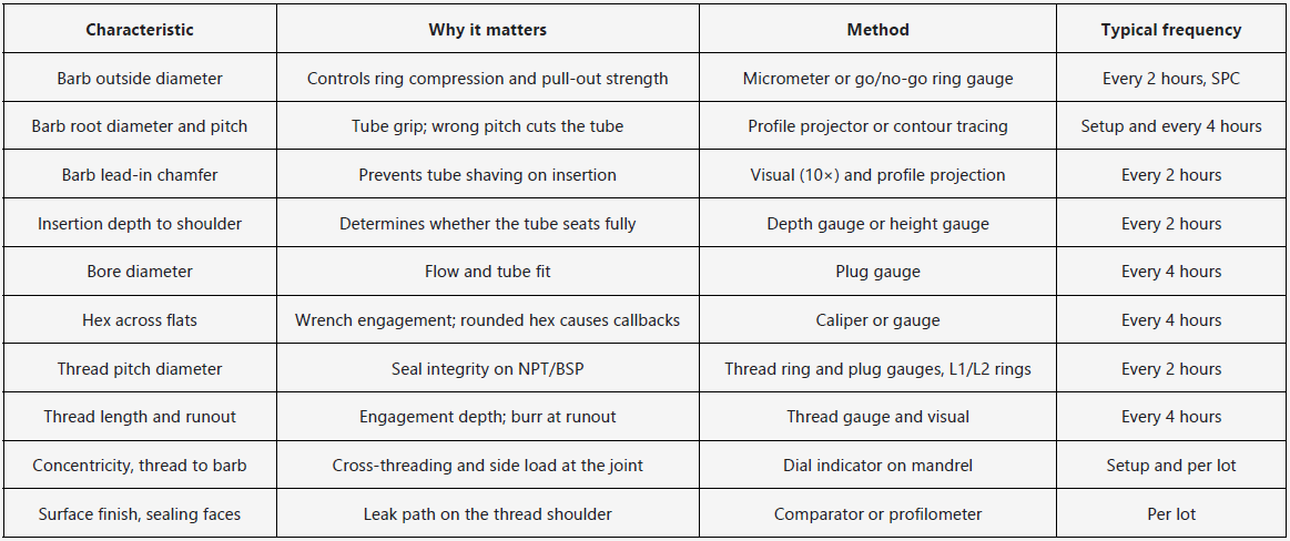
Two disciplines make this gate work. First, gauges must be calibrated on a schedule and the calibration sticker must be legible on the floor, not filed in an office. Second, the inspection sheet should record actual readings, not checkmarks. A sheet full of ticks tells an auditor nothing about drift.
Threads deserve a separate note. NPT is a tapered thread that seals on the flanks; BSPP is parallel and seals on a washer or O-ring; BSPT is tapered. A fitting made to the wrong one of these will thread in partway and leak, and the failure will be blamed on installation. Verify the thread standard on the drawing, gauge it with the correct ring, and check that the thread start chamfer is present and deburred — a missing chamfer is one of the most common causes of cross-threading in the field.
To be continued!
-